Images are representations only.
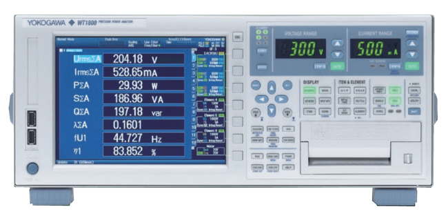
WT1800 High Performance Power Analyzer
Brand: Yokogawa Electric CorporationThe WT1800 offers innovative measurement functions for testing product efficiency and the design of inverters, motor drives, lighting systems, uninterpretable power supplies, aircraft power systems, transformer testing, and other power conversion devices.
Although the WT1800 is still available, the newer WT1800E offers higher accuracy power measurement.
Features- Voltage and current frequency bandwidth 5 MHz (-3 dB, typical)
- Reduction of low power-factor error to 0.1% of apparent power (2/3 of previous model)
- Wide voltage and current range allowing direct input
- 0.1 Hz low-speed signal power measurement and max. 50 ms high-speed data collection
- Particular voltage and current range selectable
- Support for Energy Conservation Technologies and Sustainable Energy Development
Specifications
Accuracy
- ± (0.05 % of Reading + 0.05 % of Range) - for Analog Input & Auxiliary Input
- ± 0.02 % of Reading - Timer Accuracy
- ± 0.06 % of Reading ± 0.1 MHz - Frequency Measurement
- 0.02 % of Range/°C - Voltage DC Accuracy
- 1 mA/°C for 50 A Input Element - DC Accuracy of the Direct Current Input
- 1 to 110 % - Guaranteed Accuracy Range for Voltage & Current
- 10 µA/°C for 5 A Input Element - DC Accuracy of the Direct Current Input
- 2 mV - Current Accuracy for External Current Sensor Range
- 25 mV - Voltage Accuracy
- 4 mA - Current Accuracy for 50 A Element
- 50 µA - Current Accuracy for 5 A Element
- 50 µV - Current DC Accuracy
- Line Filter is OFF (Power): (0.1 % of Reading + 0.5 % of Range) to 2 % of Range
- Line Filter is OFF (Voltage & Current): (0.05 % of Reading + 0.25 % of Range) to 1 % of Range
Applications
- Fans
- Input/Output Efficiency Measurements of Inverters
- Matrix Converters
- Mega Solar System
- Motors
- Power Generation & Conversion Efficiency Measurements in New Energy Markets, Including Photovoltaic & Wind Power Generation
- Pumps
Approvals & Certifications
- CE
- CSA
- UL
Bandwidth
- 5 MHz (-3 dB) Typical - for Voltage & Current Frequency Bandwidth
Channels
- 20-Channels - DA Output Channels Numbers
Communication
- DHCP
- Ethernet Communication
- FTP Client
- FTP Server
- GP-IB Communication
- RS-232 Communication
- SNTP
- TCP/IP Protocols
- USB-TMC - USB Communication
Consumption
- 100 mA - Max.
- 150 VA - Max.
Current
- 100 µA to 5.5 A - Current Measurement
- 20 A at DC, 10 to 45 Hz or 400 Hz to 100 kHz
Delay Time
- Within (1 microsecond + 15 Sample Intervals) - Trigger Delay Time for External Clock Input
Display
- 1024 (Horizontal) x 768 (Vertical) Dots - Total Number of Pixels
- 60,000 or more: 4-Digits - Numerical Display
- 8.4” TFT Color LCD Display
- 99,999 - Display Resolution
- Less than 60,000: 5-Digits - Numerical Display
Electrical Connectors
- Direct Input: Large Binding Post - Current Input Terminal Typical
- D-Sub 15-Pin (Receptacle) - for RGB Output
- External Current Sensor Input: Insulated BNC Connector - Current Input Terminal Typical
- Plug-In Terminal - Voltage Input Terminal Typical
- RJ45 Connector
- Typical A Connector
- Typical B Connector
Filter
- 1 MHz Analog Filter - Line Filter
- 300 kHz Analog Filter - Line Filter
- OFF, Digital Filter 100 Hz to 100 kHz (100 Hz Step) - Line Filter
- OFF, ON (Cut Off: 1 to 1,000 Hz, 1 Hz Unit Setting) - HS Filter
Frequency
- 0.1 Hz to 1 MHz - for Voltage, Current & Power
- 0.1 to 45 Hz - Measurement Lower Limit Frequency
- 0.5 to 2,600 Hz - Fundamental Frequency of the PLL Source
- 100 Hz Frequency Filter is ON at 0.15 to 100 Hz
- 2 Hz to 1 MHz - Frequency Measurement Range for Pulse Input
- 20 Hz to 1 kHz for the 1 A or 2 A Range of the 50 A Input Element - PLL Source for Harmonic Measurement
- 20 Hz to 10 kHz - Lead/Lag Phase Detection
- 48 to 63 Hz - Allowable Power Supply Frequency Fluctuation Range
- 50/60 Hz - Rated Power Supply Frequency
- OFF, 100 Hz - Frequency Filter
- Off/On, 1 kHz - Frequency Filter
Humidity
- 20 to 80 % Relative Humidity, Non-Condensing
- 30 to 75 % Relative Humidity
Input
- ± 110 % - Analog Input & Auxiliary Input
- ± 12 Vpeak - for Pulse Input
- ± 22 V - Continuous, Max.
- ± 42 Vpeak - Max.
- 0-5 V - Input Level for Remote Control
- 1,000 V, Max.
- 1,000 Vrms - Max.
- 1.5-4 kV - Instantaneous, Max.
- 10 mA-5 A (5 A Input Element) - Direct Input Current
- 10-450 A - Instantaneous, Max.
- 1-20 V - Analog Input
- 15 V or more for Voltage Input Level - PLL Source
- 1-50 A (50 A Input Element) - Direct Input Current
- 25 mV-5 V (External Current Sensor Input) - for Current
- 5 mA-2.5 A (5 A Input Element) - Direct Input Current
- 50 mA or more for Direct Current Input Level - PLL Source
- 50 mV-10 V (External Current Sensor Input) - for Current
- 500 mA-50 A (50 A Input Element) - Direct Input Current
- 600 V (Rated Voltage of EN 61010-2-030 Standard) - Current Input Terminals & External Current Sensor Input Connector for Rated Voltage to Ground
- 600 Vrms (Rated Voltage of EN 61010-2-030 Standard) - Continuous, Max.
- Approximately 1 Megaohm - External Current Sensor Input for Current
- Approximately 10 PF - Input Capacitance for Voltage
- Approximately 100 milliohms + Approximately 0.07 µH (5 A Input Element) - Direct Input for Current
- Approximately 2 milliohms + Approximately 0.07 µH (50 A Input Element) - Direct Input for Current
- Direct Input (5 A Input Element): Peak Current of 10 A or RMS of 7 A, whichever is Lower for Current Instantaneous & Continuous, Max.
- Direct Input (5 A Input Element): Peak Current of 30 A or RMS of 15 A, whichever is Lower - for Current Instantaneous, Max.
- Direct Input (50 A Input Element): Peak Current of 150 A or RMS of 55 A, whichever is Lower - for Current Instantaneous & Continuous, Max.
- Direct Input (50 A Input Element): Peak Current of 450 A or RMS of 300 A, whichever is Lower - for Current Instantaneous, Max.
- Floating Input - Voltage & Current Input Typical
- H Level: Approximately 2 V or more - Detection Level for Pulse Input
- L Level: Approximately 0.8 V or Less - Detection Level for Pulse Input
- Peak Voltage of 2 kV or RMS of 1.1 kV, whichever is Lower (If the Frequency of the Input Voltage Exceeds 100 kHz, (1200-F) Vrms or Less) - for Voltage Continuous, Max.
- Peak Voltage of 3 kV or RMS of 1.5 kV, whichever is Lower - for Voltage Instantaneous, Max.
- Peak Voltage of 4 kV or RMS of 2 kV, whichever is Lower - for Voltage Instantaneous, Max.
- Resistive Potential Method - Voltage Input Typical
- Shunt Input Method - Current Input Typical
- Sine Wave - Lead/Lag Phase Detection
- TTL - for I/O Section for Master/Slave Synchronization Signals & External Clock Input
Interface Connection
- Ethernet
- GPIB
- USB
Load
- 100 kiloohms - Min. Load for DA Output
Measuring Range
- 0.75-500 V - for Crest Factor 3
- 1.5-1,000 V - for Crest Factor 6
Measuring Time
- 1 to 1,00,00,000 - Data Measured Time for High Speed Data Capturing Function
- Infinite - Data Measured Time for High Speed Data Capturing Function
Operating Temperature
- 5° to 40° C (41° to 104° F)
Output
- ± 42 Vpeak or Less - Continuous, Max.
- ± 5 V Full Scale, Max.
Output Format
- Analog RGB Output
Power Supply
- 100-240 Vac - Rated Power Supply Voltage
- 5 V, 500 mA
- 90-264 Vac - Allowable Power Supply Voltage Fluctuation Range
Pulse Range
- 1 microsecond - Min. Pulse Width for Trigger
- 500 Nanoseconds - Pulse Width for Pulse Input
Resistance
- Approximately 1 Megaohm - Input Resistance for Motor Evaluation Function & Auxiliary Input
- Approximately 2 megaohms - Input Resistance for Voltage
Resolution
- 0.0001 Hz - Min. Frequency Resolution
- 1,024 x 768
- 16-bits
Response Time
- 5 milliseconds - Fast Data Capturing
Sample Rate
- 2 MS/s - Waveform Display
- Approximately 200 KS/s - for Analog Input & Auxiliary Input
Storage Temperature
- -25° to 60° C (-13° to 140° F)
Supply Voltage
- 750 V at 30 to 100 kHz
Temperature Coefficient
- ± 0.03 % of Range/°C - for Analog Input & Auxiliary Input
- ± 0.03 % of Reading/°C at 5° to 18° C (41° to 64.4° F) or 28° to 40° C (82.4° to 104° F)
- ± 0.05 % of Full Scale/°C - DA Output
Update Time
- 0.05 milliseconds to 2 seconds/Division However, 1/10 or Less of the Data Update Rate - Time Axis
- 1 second - Data Update Rate for High Speed Data Capturing Function
- 50 milliseconds to 20 seconds - Data Update Rate for Measurement Lower Limit Frequency
- 50 to 500 milliseconds
- Approximately 30 minutes - Warm-Up Time
Wiring
- Single-Phase 2-Wire
- Single-Phase 3-Wire
- Three-Phase 3-Wire
- Three-Phase 4-Wire
- Fans
- Input/Output Efficiency Measurements of Inverters
- Matrix Converters
- Mega Solar System
- Motors
- Power Generation & Conversion Efficiency Measurements in New Energy Markets, Including Photovoltaic & Wind Power Generation
- Pumps