Images are representations only.
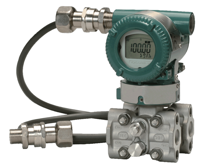
EJX910A Multivariable Transmitter
Brand: Yokogawa Electric CorporationThe EJX910A multivariable pressure transmitter delivers precise measurements of differential pressure, static pressure, and process temperature.
It features multi-sensing technology with a single-crystal silicon resonant sensor and covers multiple protocols, including HART, FOUNDATION Fieldbus, and RS485 Modbus.
Features- Utilizes DPHarp sensor technology
- Factory-programming available to specific primary elements
- Available in Mass Flow and Multi-Sensing Versions
Mass Flow Version
- ±1.0% mass flow rate accuracy
- Fully compensated mass flow
- Pulse / Contact output
- TUV SIL 2/3 Certification
Multi-Sensing Version
- ±0.04% Differential Pressure Accuracy
- ±0.1% Static Pressure Accuracy
- TUV SIL 2/3 Certification
Specifications
Accuracy
- ± (0.005 + 0.0035 URL/Span) % of Span for Capsule M (Includes Terminal-based Linearity, Hysteresis & Repeatability) - Reference Accuracy of Calibrated Span for Differential Pressure
- ± (0.005 + 0.0049 URL/Span) % of Span for Capsule H (Includes Terminal-based Linearity, Hysteresis & Repeatability) - Reference Accuracy of Calibrated Span for Differential Pressure
- ± (0.015 + 0.005 URL/Span) % of Span for Capsule L (Includes Terminal-based Linearity, Hysteresis & Repeatability) - Reference Accuracy of Calibrated Span for Differential Pressure
- ± 0.04 % of Span (Includes Terminal-based Linearity, Hysteresis & Repeatability) - Reference Accuracy of Calibrated Span for Differential Pressure
- ± 0.1 % of Span (Includes Terminal-based Linearity, Hysteresis & Repeatability) - Reference Accuracy of Calibrated Span for Absolute Pressure
- ± 0.5° C (± 0.9° F) Includes Terminal-based Linearity, Hysteresis & Repeatability, - External Temperature
- ± 1 % of Mass Flow Rate over 10:1 Flow Range (100:1 Differential Pressure Range) for Liquids & Gases - Mass Flow Reference Accuracy
Alarm
- Down-Scale: -2.5 %, 3.6 mA DC or Less
- High/Low - Contact Output Function
- Up-Scale: 110 %, 21.6 mA DC or more
Ambient Temperature Range
- -30° to 80° C (-22° to 176° F) with LCD Display
- -40° to 85° C (-40° to 185° F)
Approvals & Certifications
- Leak Test
- Material Certificate
- Pressure Test
- SIL 2 Capability for Single Transmitter Use, SIL 3 Capability for Dual Transmitter Use, IEC 61508: 2000
Approvals & Certifications
- ATEX Flameproof & Intrinsically Safe
- CE
- CSA Explosion-proof & Intrinsically Safe
- EMC EN 61326-1 Class A, EN 61326-2-3, EN 61326-2-5 (For Fieldbus)
- FM Explosion-proof, Intrinsically Safe & Non-Incendive
- IEC Ex Flameproof
- NAMUR
- PED 2014/68/EU, 97/23/EC
- UL
BSP Connection
- 1/2” BSPT Female
- 1/4” BSPT Female
Burst Pressure
- psi: 10,000 (MPa: 69, bar: 690)
Cable Length
- 1.64 to 81 feet (0.5 to 25 metres)
Communication
- Baud Rate: 1,200, 4,800, 9,600, 19,200 bit/sec
- FOUNDATION Fieldbus
- HART
- RS-485 Modbus Communication Protocol (2-Wire Half-Duplex for Communication Protocol)
Current
- 10 mA - Typical Supply Current for Modbus
- 15 mA - Max.
- 24 mA - Max.
Damping Adjustment
- 0 to 100 seconds
Diagnostics
- Configuration Error - Self Diagnostics
- CPU Failure - Self Diagnostics
- Hardware Failure - Self Diagnostics
- Heat Trace Monitoring - Advanced Diagnostics
- Impulse Line Blockage Detection - Advanced Diagnostics
- Process Alarm for Differential Pressure, Static Pressure & External Temperature - Self Diagnostics
Diameter
- 0.168” (4.3 mm) - Outside Diameter for Heat-Resistant FEP Cable with a Shield (Cable for RTD)
- 0.335” (8.5 mm) - Outside Diameter for Oil-Proof & a Heat-Resistant Cable with a Shield (Cable for RTD)
Diaphragm Material
- ASTM N10276
- Hastelloy C-276
Differential Pressure
- psi: -72.52 to 72.52 (kPa: -500 to 500, Mbar: -5,000 to 5,000)
Display
- 5-Digit - Flow, Differential Pressure, Static Pressure & External Temperature
- 6-Digit Numerical Display - Total Flow
- 6-Digit Unit Display
- Bar Graph
- LCD Display
Drain, Vent Valves & Plug
- 316 Stainless Steel - Name Plate & Tag
Duty Cycle
- 50 % Approximately (1: 2 to 2: 1)
Electrical Connectors
- 1/2” NPT Female
- G 1/2” Female
- M20 Female
Electrical Rating
- 10.5-30 Vdc, 120 mA DC, Max.
Enclosure Finish
- Anti-Corrosion Coating
- Polyurethane Paint, Mint-Green (Munsell 5.6BG 3.3/2.9 or its Equivalent)
Enclosure, Body Material
- ASTM CF-8M Stainless Steel
- Low Copper Cast Aluminum Alloy
Environmental Protection
- IP66
- IP67
- NEMA 4X
Execution Time
- 30 milliseconds - Function Block AI, SC, IT, IS, AR
- 45 milliseconds - Function Block PID
Fill Material
- Fluorinated Oil
- Silicone Oil
Flange Material
- ASTM CF-8M (Cast Version of 316 Stainless Steel. Equivalent to SCS14A) - Cover Flange
Frequency
- 10 kHz, Max.
Gasket Material
- Fluorinated Rubber - Process Connector Gasket
- PTFE Teflon - Process Connector Gasket
- Teflon-Coated 316L Stainless Steel
Gland Material
- Nickel Plating Brass - Cable Gland
Humidity
- 0 to 100 % Relative Humidity - Ambient Humidity
Indication
- Digital
Input
- RTD
Length
- 1.33” (34 mm) - Long Vent Standard Length
- 4.6” (119 mm) - Total Length of Long Vent
Load
- 0 to 1,335 ohms - for Operation - for HART Protocol Typical
- 250 to 600 ohms for Digital Communication - for HART Protocol Typical
Materials of Construction
- 304 Stainless Steel - Mounting Bracket
- 316 Stainless Steel - Name Plate & Tag
Media
- Liquids & Gases
- Steam
Mounting
- 2” Pipe Mounting Bracket
Mounting Position
- Horizontal
- Vertical
Mounting Position Effect
- Tilting up to 90° will cause Zero Shift up to 0.4 kPa
NACE & NIST
- NACE MR-0103
- NACE MR-0175, ISO 15156
NPT Connection
- 1/2” NPT Female
- 1/4” NPT Female
Nut & Bolt Material
- 316L Stainless Steel
- 660 Stainless Steel
- B7 Carbon Steel
O-Ring Material
- Buna-N - Cover O-Ring
- Fluororubber - Cover O-Ring
Operating Temperature
- -20° to 80° C (-4° to 176° F) - Oil-Prohibited Use
Output
- 0-2 Vdc - Low Level Pulse Output
- 3.8-20.5 mA - NAMUR NE43 Compliant Output Signal Limit
- 3.8-21.6 mA - Analog Output
- 4-20 mA DC (2-Wire) with Digital Communication
Output Format
- Transistor Output
Overpressure Effect
- ± 0.03 % of URL up to psi: 3,600 (MPa: 25, bar: 250) - for M & H Capsules
- ± 0.06 % of URL - for M & H Capsules (Gold-Plated Diaphragm)
Power Supply Effect
- ± 0.005 % Per Volt (21.6-32 Vdc, 350 ohms) - for HART Protocol Typical
Pressure Range
- kPa: -500 to 500
- mbar: -5,000 to 5,000
- mmWC: -10,000 to 10,000
- psi: -72.52 to 72.52
Pressure Type
- Absolute
- Differential
- Gauge
Process Connection Material
- ASTM CF-8M (Cast Version of 316 Stainless Steel. Equivalent to SCS14A)
Process Temperature
- -40° to 120° C (-40° to 248° F)
Response Time
- 200 milliseconds for M, H Capsule (Differential Pressure) & L, M, H Capsule (Static Pressure) - HART, Modbus
- 230 milliseconds for L Capsule (Differential Pressure) - HART, Modbus
- 300 milliseconds for L, M, H Capsule (Static & Differential Pressure) - Fieldbus
RTD Type
- Pt100
Sensor, Probe Type
- RTD
Stability
- ± 0.1 % of URL Per 10-Years - All Normal Operating Condition, Including Overpressure Effects
Static Pressure
- psi: -14.5 to 3,600 (MPa: -0.1 to 25, bar: -1 to 250) - Gauge Pressure
- psia: 0 to 3,600 (MPa: 0 to 25, bar: 0 to 250) - Absolute Pressure
Static Pressure Effect
- ± 0.02 % of URL Per psi: 1,000 (MPa: 6.9, bar: 69) for Capsule M - Effect on Zero
- ± 0.028 % of URL Per psi: 1,000 (MPa: 6.9, bar: 69) for Capsule H - Effect on Zero
- ± 0.05 % of URL Per psi: 1,000 (MPa: 6.9, bar: 69) for Capsule L - Effect on Zero
- ± 0.075 % of Span Per psi: 1,000 (MPa: 6.9, bar: 69) - Span Effect
Supply Pressure - Maximum
- psi: 2,300 (MPa: 16, bar: 160) - L Capsule
- psi: 3,600 (MPa: 25, bar: 250) - M & H Capsule
Supply Voltage
- 10.5-30 Vdc for Intrinsically Safe, Typical N or Non-Incendive - HART
- 10.5-32 Vdc for Lightning Protector - HART
- 10.5-42 Vdc for General Use & Flameproof Typical - HART
- 16.6 Vdc Min. Voltage - HART
- 24 Vdc Supply, up to A 570 ohms Load
- 300 V Voltage Rating - Cable for RTD
- 9-30 Vdc, 250 mW for General Use & Flameproof Typical - Modbus
- 9-32 Vdc for General Use, Flameproof Typical, Typical N or Non-Incendive - FOUNDATION Fieldbus
Temperature Effect
- ± (0.04 % of Span + 0.009 % of URL) Per 28° C (50° F) for Capsule M - Ambient Temperature Effect for Differential Pressure
- ± (0.04 % of Span + 0.0125 % of URL) Per 28° C (50° F) for Capsule H - Ambient Temperature Effect for Differential Pressure
- ± (0.055 % of Span + 0.09 % of URL) Per 28° C (50° F) for Capsule L - Ambient Temperature Effect for Differential Pressure
- ± 0.08 % of Span ± 0.018 % of URL Per 28° C (50° F) for M, H Capsule - Ambient Temperature Effect for Static Pressure
- ± 0.08 % of Span ± 0.028 % of URL Per 28° C (50° F) for L Capsule - Ambient Temperature Effect for Static Pressure
- ± 0.5° C (± 0.9° F) - Ambient Temperature Effect Per 28° C (50° F) Change
Temperature Range
- 10° to 1,050° C (18° to 1,890° F) - External Temperature Span for Capsule M, H & L
- -200° to 850° C (-328° to 1,562° F) - External Temperature Range for Capsule M, H & L
- -273° to 1,927° C (-459° to 3,500° F) - Fixed External Temperature (Pt100 ohm)
- -40° to 105° C (-40° to 221° F) - Cable for RTD
- -80° to 200° C (-112° to 392° F) - Cable for RTD
Update Time
- 1,000 milliseconds for Total Flow - HART
- 100 milliseconds - HART (Flow Rate, Differential Pressure, Static Pressure), Modbus (Differential Pressure, Static Pressure)
- 200 milliseconds for Flow Rate, Differential Pressure, Static Pressure - Fieldbus
- 400 milliseconds for External Temperature - HART, Modbus
- 800 milliseconds for External Temperature - Fieldbus
Vibration Effect
- ± 0.1 % of URL when Tested Per the Requirements of IEC 60770-1 Field or Pipeline with High Vibration Level (10-60 Hz, 0.21 mm Displacement / 60 to 2,000 Hz 3 G) - Differential & Static Pressure
- ± 0.1 % of URL when Tested Per the Requirements of IEC 60770-1 Field with General Application or Pipeline with Low Vibration Level (10-60 Hz, 0.15 mm Displacement / 60-500 Hz 2 G) - Differential & Static Pressure
- ± 0.5° C (± 0.9° F) - External Temperature
Wetted Materials
- 316L Stainless Steel
- F316L Stainless Steel
Zero Offset
- External Zero for Differential Pressure is Continuously Adjustable with 0.01 % Incremental Resolution of Span