Images are representations only.
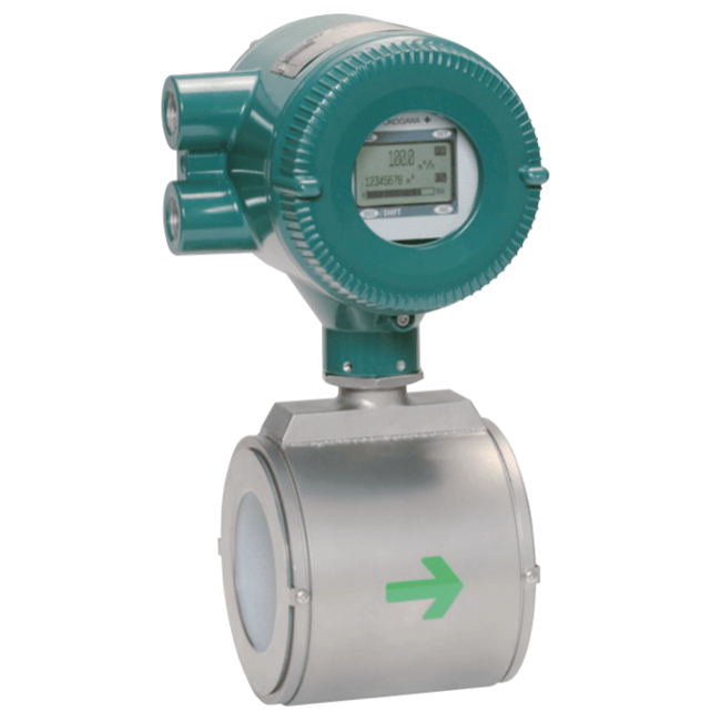
ADMAG AXR Magnetic Flow Meter
Brand: Yokogawa Electric Corporation
The ADMAG AXR two-wire loop-powered magnetic flow meter can be installed in a two-wire system.
The maximum power consumption of the AXR is 0.3W, 40 times less power draw than a traditional magnetic flow meter, resulting in CAPEX and OPEX savings.
The ADMAG AXR is the world's first two-wire magnetic flow meter which employs the fluid noise-free "Dual Frequency Excitation Method," a Yokogawa innovation, achieving excellent stability for instrumentation.
Features- 2-wire Power Loop
- An extra AC power supply is not necessary. 2-wire loop powered performance allows direct connection to DCS I/O card possible, allowing for real cost reductions.
- Reduced CAPEX and OPEX on site.
- Power consumption reduced by 40% compared to a typical 4-wire magnetic flowmeter.
- Annual CO2 emissions can be reduced from approximately 60 kg to 1.2 kg (compared to a standard 4-wire magnetic flowmeter).
- Dual Frequency Performance
- Yokogawa’s unique and advanced excitation method, "Dual Frequency Excitation," achieves stable measurement, zero stability and quick response times. The exclusive technology for stable and reliable measurement on your site.
- Noise Reduction Technology
- Flow noise reduction is further achieved by incorporating smooth mirror finished PFA liners and special surface finished electrodes. This is further enhanced with aligned super high density coils that generate a stronger magnetic field.
- SIL2 Certified
- Yokogawa believes safety should not be an option; it should be standard in all modern products. AXR is the first 2-wire magmeter of SIL2 Safety Integrity Level (IEC 61508) certified. AXR is capable of SIL2 single use and SIL3 redundant use, as standard.
- Parameter Operation
- AXR has magnet switches for parameter setting. Users can access the functions without removing the case cover in hazardous, humid, and dusty environments.
- Adhesion Diagnostic Level Function
- The electrode is one of the most important parts of a magnetic flow meter. Only ADMAG flow meters have "Adhesion Diagnostic Level Function". It diagnoses the condition of electrode surface and indicates the adhesion/coating in 4 levels. Users can change the detection level (threshold) depending on each individual process condition. This allows for predictive maintenance and reduced operating costs.
- Alarm Indication
- ADMAG AXR employs a full-dot matrix LCD indicator. It can display up to 3 lines as required by the user and is available in multiple languages. If an alarm is triggered, a clear message is displayed along with a solution.
- High Accuracy
- The ADMAG AXR performs 0.5% of rate under normal flow rate conditions.
Specifications
Accuracy
- 0.5 % of Rate
Alarm
- 20.5 mA - Process Alarm, Setting Alarm
- 21.6 mA or more - System Alarm, Process Alarm, Setting Alarm
- 3.2 mA or Less - System Alarm, Process Alarm, Setting Alarm
- 3.8 mA - Process Alarm, Setting Alarm
- 4 mA - Process Alarm, Setting Alarm
- Down-Scale: -5 %, 3.2 mA DC or Less - Burn-Out
- Up-Scale: 110 %, 21.6 mA DC or more (Standard) - Burn-Out
Ambient Temperature Range
- 20° ± 5° C (9° F)
- -40° to 55° C (-40° to 131° F) - General-purpose Use
Approvals & Certifications
- ATEX EN 60079-0, EN 60079-1, EN 60079-7, EN 60079-11, EN 60079-31, DEKRA 11-ATEX-0144
- CE
- CSA C22.2 No.0, C22.2 No.0.4, C22.2 No.0.5, C22.2 No.25, C22.2 No.30, C22.2 No.94, C22.2 No.157, C22.2 No.61010-1, Class I, Groups A, B, C, D, Class II, Groups E, F, G, Class III
- EMC EN 61326-1 Class A, EN 61326-2-3
- FM FM3600, FM3610, FM3615, FM3810, ANSI/NEMA 250, Explosion-proof for Class I, Div. 1, Groups A, B, C, D, Dust-Ignition-proof for Class II/III, Div. 1, Groups E, F, G
- IECEx IEC 60079-0, IEC 60079-1, IEC 60079-7, IEC 60079-11, IEC 60079-31, Ex d E Ia IIC T6 to T4 Gb
- TIIS Ex d E [ia] IIC T4
Approvals & Certifications
- Calibration
- Hydrostatic Pressure Test
- Material Certificate
- SIL 2 Capability for Single Flowmeter Use, SIL 3 Capability for Dual Flowmeter Use, IEC 61508: 2000, Part 1 to Part 7
- TÜV (Technischer Uberwachungsverein)
BSP Connection
- G 1/2” Female
Cable Length
- 6,562 feet (2,000 metres)
Cable Material
- Polyvinyl Chloride Insulated & Sheathed Portable
Communication
- BRAIN
- HART
Cover Material
- Aluminum Alloy
Current
- 25 mA or Less for 1 Minute at 500 Vac between Power Supply/Digital Output & Functional Grounding
- 3.2 mA (-5 %) or Less - Current Output
- 6 mA or Less for 1 Minute at 100 Vac between Power Supply / Digital Output & Functional Grounding
Diagnostics
- Process, System, Setting Alarm & Warnings (Self Diagnosis)
Diameter
- With No Glands: 0.26” to 0.47” (6.5 to 12 mm)
- With Plastic Glands: 0.24” to 0.47” (6 to 12 mm)
- With Waterproof Glands & Waterproof Glands with Union Joints: 0.41” to 0.45” (10.5 to 11.5 mm)
Display
- Full Dot-Matrix LCD (128 x 64 Pixels)
Distance
- 0.8 Kilometers - Analog I/O Module (For Prosafe-RS)
- 1.4 Kilometers for Analog I/O Module (For Prosafe-RS)
- 6” (15 cm) or more - Distance from Other Power Line
- Up to 2 Kilometers when A CEV Cable is used - Communication Distance (JUXTA, Distributor, I/O Module, Signal Conditioner Card)
Duty Cycle
- 50%
Electrical Connectors
- ANSI 1/2” NPT Female
- ISO M20 x 1.5 Female
- JIS G 1/2” Female
- M4 Screw Terminal
Electrical Protection
- Lightning Protection
Electrical Rating
- 120 mA DC at 30 Vdc
Enclosure Finish
- Corrosion-Resistant Coating
- Epoxy Resin Coating
- High Anti-Corrosion Coating
- Mint Green Paint (Munsell 5.6 BG 3.3/2.9 or its Equivalent) - Coating Color
- Polyurethane Coating
Enclosure, Body Material
- 304 Stainless Steel
- Aluminum Alloy - Converter Material
- Carbon Steel-JIS SPCC Equivalent
Environmental Protection
- IP66
- IP67
- NEMA 4X
Excitation Voltage
- 29 V, Max.
Flange Material
- 304 Stainless Steel
- Carbon Steel (JIS SS400 or SFVC 2A) - Flange & Mini-Flange Material
- JIS SUS430 ASTM 4300 / DIN X6Cr17 / EN 1.4016 Equivalent - Mini Flange
- Stainless Steel-SCS13 - Mini Flange, Pipe
Flange Size - 1-1/2” (DN 40)
- 1-1/2” (DN 40) - 150# ANSI
- 1-1/2” (DN 40) - 300# ANSI
- 1-1/2” (DN 40) - JIS 10K
- 1-1/2” (DN 40) - JIS 20K
- 1-1/2” (DN 40) - PN 10
- 1-1/2” (DN 40) - PN 16
- 1-1/2” (DN 40) - PN 40
Flange Size - 1” (DN 25)
- 1” (DN 25) - 150# ANSI
- 1” (DN 25) - 300# ANSI
- 1” (DN 25) - JIS 10K
- 1” (DN 25) - JIS 20K
- 1” (DN 25) - PN 10
- 1” (DN 25) - PN 16
- 1” (DN 25) - PN 40
Flange Size - 2-1/2” (DN 65)
- 2-1/2” (DN 65) - 150# ANSI
- 2-1/2” (DN 65) - 300# ANSI
- 2-1/2” (DN 65) - JIS 10K
- 2-1/2” (DN 65) - JIS 20K
- 2-1/2” (DN 65) - PN 10
- 2-1/2” (DN 65) - PN 16
- 2-1/2” (DN 65) - PN 40
Flange Size - 2” (DN 50)
- 2” (DN 50) - 150# ANSI
- 2” (DN 50) - 300# ANSI
- 2” (DN 50) - JIS 10K
- 2” (DN 50) - JIS 20K
- 2” (DN 50) - PN 10
- 2” (DN 50) - PN 16
- 2” (DN 50) - PN 40
Flange Size - 3” (DN 80)
- 3” (DN 80) - 150# ANSI
- 3” (DN 80) - 300# ANSI
- 3” (DN 80) - JIS 10K
- 3” (DN 80) - JIS 20K
- 3” (DN 80) - PN 10
- 3” (DN 80) - PN 16
- 3” (DN 80) - PN 40
Flange Size - 4” (DN 100)
- 4” (DN 100) - 150# ANSI
- 4” (DN 100) - 300# ANSI
- 4” (DN 100) - JIS 10K
- 4” (DN 100) - JIS 20K
- 4” (DN 100) - PN 10
- 4” (DN 100) - PN 16
- 4” (DN 100) - PN 40
Flange Size - 6” (DN 150)
- 6” (DN 150) - 150# ANSI
- 6” (DN 150) - 300# ANSI
- 6” (DN 150) - JIS 10K
- 6” (DN 150) - JIS 20K
- 6” (DN 150) - PN 10
- 6” (DN 150) - PN 16
- 6” (DN 150) - PN 40
Flange Size - 8” (DN 200)
- 8” (DN 200) - 150# ANSI
- 8” (DN 200) - 300# ANSI
- 8” (DN 200) - JIS 10K
- 8” (DN 200) - JIS 20K
- 8” (DN 200) - PN 10
- 8” (DN 200) - PN 16
- 8” (DN 200) - PN 40
Flow Rate
- 0 to 18,850 LPM (0 to 4,979 gpm) - Max.
- 0 to 565.5 LPM (0 to 149.4 gpm) - Min. Span Flow Rate (1 feet/sec)
Fluid
- Gas
- Liquid
Gasket Material
- Chloroprene Rubber
- Fluororubber (Acid Resistant & Alkali Resistant) for PVC Pipes (Viton)
- PTFE-Sheathed Non-Asbestos
Humidity
- 0 to 100 % - Ambient Humidity
Input Impedance
- 10 kiloohms or more at 2.4 kHz - Communicating Device
Insulation Resistance
- 100 megaohms or more at 50 Vdc between Power Supply / Digital Output & Functional Grounding
- 20 megaohms or more at 100 Vdc between Power Supply/Digital Output & Functional Grounding
Load
- 0.22 µF or Less - Load Capacitance
- 3.3 MH - Load Inductance
Maximum Current
- 17 mA - Intrinsically Safety Circuit
- 600 A (8/20 μs) - Allowable Current
Maximum Voltage
- 14 V - Intrinsically Safety Circuit
Mounting
- M4 Screw
Mounting Position
- Vertical
NPT Connection
- 1/2” NPT Female
Nut & Bolt Material
- Carbon Steel
Operating Temperature
- -20° to 55° C (-4° to 131° F) - Indicator Operating Range
Output
- 0-2 Vdc - Low Level
- 10.4 mA Current Output - During Zero Adjustment (450 seconds)
- 2 Vdc, 120 mA - Max.
- 3.8-20.5 mA (-1.25 to 103.13 %)
- 30 Vdc, Max.
- 4-20 mA DC, 2-Wire System - Current Output
Output Format
- Alarm Output
- Current Output
- Pulse Output
Power
- 0.12 W - Max.
Power Supply
- 14.7 to 42 Vdc, 2-Wire System - Integral Flowmeter Operating Voltage Range
- 42 Vdc, Max.
Process Connection Style
- Wafer
Process Temperature
- -40° to 130° C (-40° to 266° F)
Pulse Range
- 0.0001 to 10,000 Pulse/second - Pulse Output Rate
- 0.05 to 100 milliseconds - Pulse Width
Repeatability
- ± 0.2 % of Rate (When the Flow Velocity is 1.5 m/sec Toward 2 m/sec of Setting Span)
Resistance
- 10 ohms or Less - Grounding Resistance when Lightning Protector is Used
- 100 ohms or Less - Grounding Resistance
- 250 to 600 ohms (Including Cable Resistance) - Load Resistance
Ring Material
- 316 Stainless Steel - Grounding Ring (Plate Typical)
- Hastelloy C-276 - Grounding Ring (Plate Typical)
- Stainless Steel-JIS SUS316L or ASTM 316L (AISI 316L Stainless Steel / EN 1.4404 Equivalent) - Grounding Ring (Plate Typical)
Rotation
- 180° Rotated Converter to Change the Direction of Electrical Connection
- 90° Rotated Converter to Change the Direction of Electrical Connection
- -90° Rotated Converter to Change the Direction of Electrical Connection
Size
- 1 to 8” (25 to 200 mm): 10 μS/cm or Larger - Fluid Conductivity
- 1” to 4” (25 to 100 mm) - Wafer & Flange Typical
Supply Voltage
- 14.7-32 Vdc for Lightning Protector
- 14.7-42 Vdc for General-purpose Use & Explosion-proof Typical
- 20.6-42 Vdc - Communication Requirement for BRAIN, HART
- 250 Vac - Electrode Circuit, Allowable Voltage (50/60 Hz)
- 250 Vdc - Allowable Voltage
Switch Quantity
- 4 Magnet Switches (Including Push Switches) - Operational Switch
Temperature Range
- -20° to 130° C (-4° to 265° F) - Fluid Temperature
Time Constant
- 1 to 200 seconds (63 % Response) - Damping Time Constant
- 5 seconds - Default Damping Time Constant
Vibration
- 9.8 m/sec² or Less (500 Hz or Less)
Wetted Materials
- 316 Stainless Steel - Grounding Ring/Grounding Electrode
- 316L Stainless Steel - Electrode
- Fluorocarbon PFA Lining
- Hastelloy C-276 Equivalent - Electrode
- Platinum Iridium - Electrode
- Tantalum - Electrode
Wiring
- 0.5 to 1.5 mm² - Stranded Wire: Nominal Cross Section
- 0.5 to 2.5 mm² - Single Wire: Nominal Cross Section
Documentation
Product Manuals
Brochure
- Brochure A pdf 3.1 MB
- Brochure B pdf 2.7 MB
- Brochure C pdf 4.5 MB
- Brochure D pdf 7.3 MB
- Brochure E pdf 1.6 MB
- Brochure F pdf 1.4 MB
- Brochure G pdf 1.6 MB
- Brochure H pdf 934 KB
- Brochure I pdf 1.2 MB
- Brochure J pdf 767 KB
- Brochure K pdf 960 KB
- Brochure L pdf 1.3 MB
- Brochure M pdf 1.2 MB
- Brochure N pdf 1.4 MB
- Brochure O pdf 1.2 MB
- Brochure P pdf 769 KB