Images are representations only.
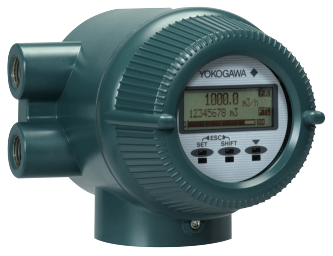
AXFA14G/C Magnetic Flow Meter
Brand: Yokogawa Electric CorporationThe AXFA14 magnetic flow meter remote converter is a sophisticated product with outstanding reliability and ease of operation, developed on the basis of decades of field proven experience.
The AXFA14 employs an LCD indicator, infra-red switches, and "Easy Setup" parameters to ensure substantially improved ease of maintenance.
The combination of a replaceable electrode type flowtube and diagnostics to detect the adhesion level on the electrodes dramatically improves maintainability.
The AXFA14 also employs the fluid noise free "Dual Frequency Excitation Method" and the newly added "Enhanced Dual Frequency Excitation Method" as an option for more difficult applications to ensure greater stability and quicker response.
Features- User-oriented Functionality
- Fluid Adhesion Level Diagnosis
- Flexible Electrical Connection Direction
- Clear and Versatile Indications
- "Easy Setup" Parameters “◊”
- Operation Immediately after Installation
- Compact and Light-weight Converter
- Expansion of Product Lineup
- Improved Accuracy Specification
- Enhanced Performance and Specifications
- Enhanced Dual Frequency Excitation Method
- Improved Minimum Conductivity
- High-Speed Pulse Output: “◊”
- Versatile Input/output Function “◊”
Specifications
Accuracy
- ± 0.2 % of Rate
- 0.18 % of Rate + 0.2 mm/sec
- 0.2 % of Reading - High Accuracy Calibration
- 0.35 % of Rate
- 0.35 % of Reading
Alarm
- 2.4 mA or Less
- Fixed to 4 mA, 21.6 mA or more or HOLD
Ambient Temperature Range
- -20° to 60° C (-4° to 140° F) - for TIIS
- -40° to 60° C (-40° to 140° F)
Approvals & Certifications
- ATEX, EN 60079-0, EN 60079-1, EN 60079-31, Certificate: DEKRA 15-ATEX-0029 X, Ex db IIC T6 Gb, Ex Tb IIIC T75° C Db
- CE
- CSA C22.2 No 0, 0.4, 0.5, 25, 30, 94, 61010-1-12, 61010-2-030-12, Explosion-proof for Class I, Div. 1, Groups A, B, C, D, Dust-Ignition-proof for Class II/III, Div. 1, Groups E, F, G CSA E79 - CAN/CSA-E79-0, CAN/CSA-E79-1, Certificate: 1481213
- EMC EN 61326-1 Class A, EN 61326-2-3, EN 61326-2-5, EN 61000-3-2 Class A, EN 61000-3-3
- FM FM3600, FM3615, FM3810, ANSI/NEMA 250, Explosion-proof for Class I, Div. 1, Groups A, B, C, D, Dust-Ignition-proof for Class II/III, Div. 1, Groups E, F, G
- IEC Ex IEC 60079-0, IEC 60079-1, IEC 60079-31, Certificate: IECEx dEK 15.0022 X, Ex db IIC T6 Gb, Ex Tb IIIC T75° C Db
- TIIS Ex d IIC T6, Certificate: TC16678
Cable Material
- Polyethylene Insulated PVC Sheathed
Communication
- BRAIN
- FOUNDATION Fieldbus
- HART
- PROFIBUS PA
Consumption
- 12 W - Max.
Cover Material
- Aluminum Alloy - Converter Material
Damping Adjustment
- 0.1 to 200 seconds - Damping Time Constant
- 3 seconds - Default
Diagnostics
- Process, System, Setting Alarms & Warnings
Display
- Full Dot-Matrix LCD (32 x 132 Pixels)
Distance
- 6” (15 cm) - Distance from Power Line
- Up to 1.5 Kilometers - Communication Distance
Duty Cycle
- 50 % - Pulse Output
Electrical Connectors
- ANSI 1/2” NPT Female
- ISO M20 x 1.5 Female
- JIS G 1/2” Female
- M4 Screw Terminal
Electrical Protection
- Lightning Protection
Enclosure Finish
- Corrosion-Resistant Coating
- Mint Green (Munsell 5.6 BG 3.3/2.9 or its Equivalent)
Enclosure, Body Material
- Aluminum Alloy - Converter Material
Environmental Protection
- IP66
- IP67
- NEMA 4X
Excitation Voltage
- 140 V, Max.
Humidity
- 0 to 100 % - Ambient Humidity
Input Impedance
- 10 kiloohms or more at 2.4 kHz
Insulation Resistance
- 100 megaohms at 500 Vdc - between Power Supply Terminals & Ground Terminal, between Power Supply Terminals & Input/Output / Excitation Current Terminals
- 20 megaohms at 100 Vdc - between Ground Terminal & Input/Output/Excitation Current Terminals, between Input/Output/Excitation Current Terminals
Load
- 0.22 µF or Less - Load Capacitance
- 3.3 MH or Less - Load Inductance
Materials of Construction
- Ceramics Lining
- EPDM Rubber Lining
- Natural Soft Rubber Lining
- PFA Lining
- Polyurethane Rubber Lining
Mounting
- 2” Pipe Mount
Operating Temperature
- -20° to 60° C (-4° to 140° F) - Indicator’s Operating Range
Operating Voltages
- 20.4-28.8 Vac
- 20.4-28.8 Vdc
- 80-264 Vac
- 90-130 Vdc
Output
- 1.6 Vdc, 200 mA - Max.
- 30 Vdc (OFF) / 200 mA (ON) - One Pulse Output, One Alarm Output, Two Status Outputs
- 30 Vdc, Max.
- 4-20 mA DC (Load Resistance: 750 ohms, Max.
- 9-32 Vdc, 15 mA - Digital Communication
Power Supply
- 100-120 Vdc, 24 Vac/Vdc
- 100-240 Vac, 50/60 Hz
- 24 Vac, 50/60 Hz - Rated Power Supply
- 24 Vdc - Rated Power Supply
Pulse Range
- 0.0001 to 10,000 Pulse/second - Output Rate
- 0.05 to 100 milliseconds - Pulse Width
Repeatability
- ± 0.05 % of Rate ± 0.5 mm/sec (V< 1 m/sec (3.3 ft/sec))
- ± 0.1 % of Rate (V≥ 1 m/sec (3.3 ft/sec))
Resistance
- 10 ohms or Less - with Lighting Protector
- 100 kiloohms or more (OFF) - Load Resistance
- 100 ohms or Less - Grounding Resistance
- 200 ohms or Less (ON) - Load Resistance
- 250 to 450 ohms (Including Cable Resistance) - Load Resistance for BRAIN Communication
- 250 to 600 ohms (Including Cable Resistance) - Load Resistance for HART Communication
Supply Voltage
- 1,400 Vac for 2 seconds between Power Supply Terminals & Ground Terminal, between Power Supply Terminals & Input/Output Terminals - Withstand Voltage
- 130 Vdc - Max.
- 160 Vac for 2 seconds between Excitation Current Terminal & Ground Terminal - Withstand Voltage
- 250 Vac - Max.
- 350 Vac for 2 seconds between Excitation Current Terminal & Input/Output Terminals - Withstand Voltage
Vibration
- 9.8 m/sec² or Less (Frequency of 500 Hz or Less) in Conformity with IEC 60068-2-6 (SAMA31. 1-1980)
Documentation
Product Manuals
- Instruction Manual A pdf 6.9 MB
- Instruction Manual B pdf 876 KB
- Instruction Manual C pdf 2.4 MB
- Instruction Manual D pdf 1.8 MB
- Instruction Manual E pdf 791 KB
- Instruction Manual F pdf 5.3 MB
- Instruction Manual G pdf 10.7 MB
- Instruction Manual K pdf 532 KB
- Instruction Manual L pdf 59 KB
- Instruction Manual M pdf 547 KB
- Instruction Manual N pdf 1,017 KB
- Instruction Manual O pdf 94 KB